

How does an X-ray scanner find glass fragments in glass?
Glass fragments in food, medicine or cosmetics are a danger to health. It is extremely important for every manufacturer of these products to find and remove such impurities before a product reaches the consumer.
High-quality glass is an effective and hygienic packaging option, but with it comes the risk of small glass fragments contaminating the product during the filling process. These fragments are barely visible to the naked eye and even for modern technology it takes a significant effort to eliminate this threat.
CASSEL XRAY SHARK® X-ray machines with sideview (or sideshoot) units are specially designed to detect these contaminants. They detect glass splinters in the product even if the packaging is also made of glass or the individual product is additionally packed in a cardboard box.

XRAY SHARK XS GIG: Sideshoot X-ray scanner, that is perfectly adapted to glass-in-glass inspection.
Can X-ray Inspection Systems Detect Glass Contaminants within a Glass Container?
How does an X-ray scanner find impurities?
X-ray machines recognize different materials by their densities, which cause different degrees of attenuation (absorption) of the X-ray beam. A high attenuation leads to a dark gray color value in the X-ray image, a low attenuation to a light gray color value.
A glass bottle has a higher density than the liquid filled in it, which is shown as a darker gray color value in the X-ray image: the bottle’s outline can be clearly identified within the X-ray image. If there is a foreign body in the liquid, it is visible as a “dark spot” within the bottle contour in the X-ray image. The software automatically identifies the foreign object due to a variation in the image.
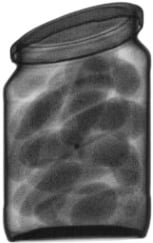
A good example is a jar with pickles.
- Glass container: High density or absorption = dark gray
- Pickle juice: Low density or absorption = light gray to white
- Pickles: Average density or absorption = light gray
- Foreign body: Medium to high density = medium gray, separate from the packaging
Different shades of grey in the X-ray image
Simply put, it can be said that the X-ray images show density contrasts because the X-ray’s absorption strength varies for different materials. This variation is represented by different gray levels. The grayscale goes from black to white and is divided into 255 levels (grayscale values). White corresponds to a low absorption and black to a high absorption of the X-ray beam.

The grayscale is used to set up thresholds values to distinguish areas in the X-ray image. The density/absorption of a material determines the degree of blackening. The absorption strength also depends on the thickness of a material. If the X-ray beam passes through a large amount of material on its way to the detector, it is strongly attenuated. If the X-ray beam passes through a small amount of material on its way to the detector, it is mildly attenuated. Both thickness and density of the material therefore are highly important.
How are different greyscales created in an X-ray image?
Example: Objects a, b, c in the figure on the right are different foreign objects in a product.
- (a) has a low density and a medium diameter.
- (b) has a high density and a large diameter.
- (c) has a high density (just like b) and a small diameter.
The X-ray images are quite different for the three objects.
For (b) it shows the strongest blackening (large diameter and high density).
Object (a) shows medium blackening (lower density, and medium diameter).
The least blackening comes from (c) (high density, but very small diameter).
Thus the diameter in line with the beam plays a role in the intensity of the blackening in the X-ray image.

In the case of an irregularly shaped foreign body, there are different diameters depending on the viewing direction. If you look at the same foreign body in two different orientations, this becomes clear.
Influence of the orientation of an object on the gray shading
The diagram on the right shows the importance of the orientation of an object in the X-ray unit. The glass container holds a small plastic plate.
Left: The platelet lies transverse to the X-ray beam. The thickness in beam direction is small and therefore little radiation is absorbed. The result is a low blackening in the X-ray image and almost no contrast between the foreign body and the product. The platelet in the X-ray image on the lower left is hardly visible.
Right: The same foreign body, now aligned with the X-ray beam. With a large diameter in beam direction, a lot of radiation is absorbed. Result: A strong blackening in the X-ray image and a significant contrast between the foreign body and the product. The platelet is clearly visible in the X-ray image on the bottom right.
The path length of the X-ray beam through a material therefore significantly determines the degree of blackening. An unfavorable orientation of the foreign body can lead to a failure within the recognition process.


However, an unfavorable orientation of a foreign body does not necessarily result in poor detectability of the foreign body.
If, in addition to the X-ray beam, which sees the foreign body in an unfavorable orientation (short path length), a second X-ray beam is used, and positioned 90° to the first, the second beam will see the foreign body in a different orientation (long path length).
This second beam is now more absorbed and thus produces a darker image resulting in the detection of the foreign body.
Density and thickness of glass containers
Glass containers are a challenge in several respects: On the one hand, glass has a high density, which the X-ray beam must pass through before it even hits the product to be examined. An X-ray machine that aims to find a contamination must therefore be able to penetrate the large thickness of the glass container and yet still detect the contamination behind it.
For this purpose CASSEL Inspection uses high power emitters, which apply the necessary power to penetrate the glass container and ensure a good contrast between the product and the foreign object.
Convex bottoms of glass containers
The bottom of glass containers is usually quite thick and often curved inwards. Contaminants that sink to the bottom therefore often collect at the edge of the container bottom. However, this is exactly where the packaging reaches its maximal thickness. This can lead to “blind spots” (non-inspected areas).
The graphics on the right illustrate this: if the impurities are higher than the curvature of the bottom, they can be detected. If they are lower, however, they “can be hidden” behind the curvature if only one X-ray source is used.
Similar to an unfavorable orientation of the contamination in the product, the detection performance of the X-ray inspection is improved by using a second X-ray source.
This means, the X-ray unit generates two images from two different perspectives. Contaminants that are “hidden” behind the curvature in one image appear next to it in the second image.


The important role of software in X ray scanners
As explained, the X-ray detectors visualize various densities of different materials. In addition, they must be able to screen all “corners” of the examined product, since a glass splinter in the X-ray image can also “hide” on the wall or at the bottom. This precisely illustrates the difficulty in finding glass splinters in glass containers: glass splinters have the same density as the glass packaging, but at the same time they often collect at the bottom, where inspection is particularly difficult. So how does the X-ray machine detect these glass fragments?
First, you need X-ray images from different perspectives so that no splinter can hide. Next, the X-ray software as well as some additional factors come into play.
- A fragment of glass usually has a higher density than the product under investigation, e.g. a beverage. So it attenuates the X-rays more than the product does (more absorption).
- The glass fragment in the product also displaces the product at this spot. The product with low absorption is locally replaced by a glass fragment with higher absorption. This absorption difference between product and glass fragment is visible as additional blackening in the image.
This additional blackening, which can be very weak, must be visible to the X-ray machine.
The software must therefore reliably “detect” this darker gray coloration in the image (glass fragment) in order to distinguish it from other, darker gray colorations (bottle contour, cap, etc.).
Various mask and filter functions are available for this purpose. The most important are the filters for contrast enhancement and the masking functions.
The contrast enhancement makes blurred edges in the X-ray image stand out better. This makes it easier to distinguish “shadows” from their surroundings and identify them as possible foreign objects – if their shape does not “fit” the product and its packaging.
To enable the software to recognize what belongs to the product and what does not, various so-called masks are available. They mark which shapes in the image belong to the packaging – so the software can filter them out as “harmless”.
These filters must be highly flexible so they can process all shapes correctly even from different angles and under different lighting conditions.
CASSEL XRAY SHARK® scanners work with over 40 different algorithms which make these filters and masks highly flexible; for a wide range of angles and illumination conditions. With this range of capabilities, the detection of glass splinters is possible even under difficult conditions, such as in glass containers.

The technical expertise for this article was provided by Dr. Lars Raue (R&D)
Lars wrote his doctoral thesis in the Department of Microstructure Physics & Metal Forming at the Max Planck Institute for Iron Research in Düsseldorf and received his PhD from the RWTH Aachen university. Afterwards he worked in the field of material science at the Crystallography Department of the Geosciences Center of the University of Göttingen as well as for the University Medical Center Göttingen. Here he gained extensive experience in X-ray technology, e.g. through high-pressure radiographic investigations of the polymorphism of drugs, the planning, construction and commissioning of X-ray diffractometers and various experiments at all major German synchrotron facilities. Since 2016 Lars develops industrial X-ray applications for CASSEL Inspection.